Wednesday, December 27, 2006

Studying the Setback Variable of Small Boundary Rigs


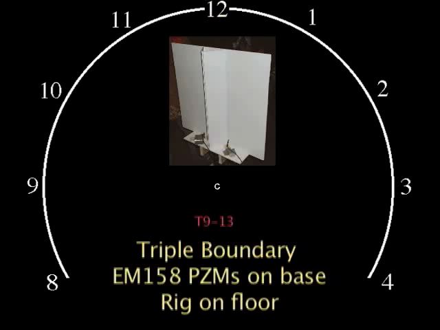
Acting on Curt Olson's suggestion, one variable we tested was the distance from the leading edge of our small, head-spaced, parallel boundary rigs to the diaphragm of the Primo EM158 omni-directional capsules. Curt calls this the "setback." We created impulses by striking two large nail "spikes" together in a circle 30 feet away from the mic set-up area. The building was a 100' X 60' wooden barn with a concrete floor. All mic rigs faced the 12 o'clock sound source.

For best results, monitor the following tests with good headphones or near field speaker monitoring.


Here are two QuickTime test movies presenting a progression of four set back distances from three clock positions: 10 o-clock, 12 o-clock and 2 o-clock:

Mic Station 7 Setback Distances: 3" -> 2.5" -> 1.5" -> 1" Large Movie 7mb (48K/16 sound) SMALL Movie 1mb (compressed sound)

Mic Station 14
Setback Distances: 2" -> 1.5" -> 1.0" -> .5" Large Movie 7mb (48K/16 sound) SMALL Movie 1mb (compressed sound)


Next, the same sound samples edited to "toggle" back-and-forth between the maximum and minimum inset distances for both mic stations:

Mic Station 7 Setback Distances: 3" -> 1" Toggle
Large Movie 13mb (48K/16 sound) SMALL Movie 2mb (compressed sound)

Mic Station 14 Setback Distances: 2" -> .5" Toggle Large Movie 13mb (48K/16 sound) SMALL Movie 3mb (compressed sound)

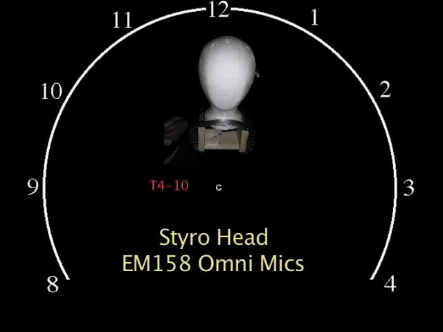
To my ears, the nail strikes seem further away at the .5": and 1.0" setback distances compared to the larger distances. This reminded me of omni-directional mic performance in open air, so I added recordings from another rig, this one with front-facing 7" spread omni mics using the same model mic capsules and a single 18" by 18" single cardboard baffle. The sound sources are 30 feet away at 10 0-clock, 12 o-clock and 2 o-clock:

Mic Station 7: 3" Setback -> 1"
Setback -> Omni A/B Large Movie 7mb (48K/16 sound) SMALL Movie 1mb (compressed sound)

Mic Station 14: 2" Setback -> .5" Setback -> Omni A/B Large Movie 9mb (48K/16 sound) SMALL Movie 2mb (compressed sound)

Assessments Even with headphones, perceptible differences are subtle at first impression, but with repeated playing, one can detect that the smaller setback distances of .5" and 1.0" seem to create the impression of a larger or more "airy" space.


click on image to view larger

The left-front corner of the wooden barn has a 18' X 18' walled-in area whereas the right side of the barn is open. The sound impulses created on the right side of the room produce louder, longer reverberations. In the above sonogram, one can see the additional volume (blue and red areas) with the .5" setback and the A/B Baffle impulses over the 2" inset in the third and fourth harmonics of the .5" setback and the fourth and fifth harmonics of the A/B rig. The A/B rig has more brightness at the highest harmonics at 12K Hz and 19Khz. I believe the first strike on the left side with the pronounced 3rd harmonic @5800Hz channel was probably due to a performance difference. Another factor that could be adding to the impression of the spaciousness and with the .5" setback is lower volume of and masking from the 1st and 2nd harmonics at 1700Hz and 3400Hz. I


click on image to view larger

The low frequency drones of a nearby factory penetrating the walls makes it hard to evaluate differences in spatial rendering below 1700Hz (which is a very important part of the spectrum to study when considering "spaciousness.") There could be less response in the spectrum between ~400-800 Hz with the .5" setback and A/B rigs (see circled areas above), but variations in the background sounds during the test moments makes this too difficult to judge.

Does the shorter inset have a negative impact on localization within the stereo field? It doesn't seem to. It might even be better:

Mic Stations 14: Quick Sweep of All Clock Positions with 2" and .5" Setbacks Large Movie 5mb (48K/16 sound) SMALL Movie 1mb (compressed sound)


Conclusions There's enough performance difference between the short and long setback distances to merit experimenting with this variable in the field. Its too early to suggest that our Parallel Boundary rigs will generally produce more spaciousness in the stereo image with a small sebacks, but the possibility exists. The similarities in performance between these small setback distances and the A/B baffle rig suggest to me that the small setback distances are allowing the capsules to perform more as they would in the open air-iin this case used with a baffle to lessen high Hz cross-over from the other side with a head-like spacing. These traits are common to both the wooden Parallel Boundary and A/B cardboard baffle rigs. Rob D.

Anthony Lopez: Styro Head Test

As I said in my previous post, I really enjoyed the Styro head with the EM158 omni mics. This rig seemed to be the most accurate in every aspect: localization, depth, and architectural mapping. There are three tests with stryo heads, and of the three, T4-10 is the most successful. For reiteration, here is my edited previous description of the rig in regards to localization, depth, and architecture.

T4-10 Styro Head EM158 Omni Mics.

A) This rig does an excellence job of recreating localization for the human head. When I close my eyes, without looking at the graphic, each clink has a physical presence in my ears and is easily mapped out. Because the capsules are front facing they seem to favor 10-2 o’clock, which makes it harder for me to discern the location of these because the clinks are more immediate and are being amplified by the shape of the head, in much the same way the boundary insets effect the sound on a parallel boundary mic. Here is a comparison of the two rigs for clarification.


Both of these tests display a lot of space and easy localization. However, I think the styro head provides the most.

B) When comparing the depth of the parallel boundary and the styro head, the styro head seems to have a more realistic sense of depth; although, the parallel comes close. Sometimes the depth seems difficult to discern because of the variable amount of force that was used to clink the nails. The clinks sound further away at 8, 3, and 4. And closer at 9, 10, and 11. At 12 the rig seems to have the correct depth. This is perhaps due to the 6” headspace on the foam head allowing the stereo image of the sound to reach both ears properly. At the other positions the opposite capsule becomes a victim of head shadow, something the human head experiences, which causes one ear/capsule to receive more sound sooner than the opposite one.

The main difference between these two rigs is the type of boundary they offer. The parallel has a dense, flat, wooden boundary. The styro has a foam, curved boundary. As has been suggested by Rob D. in class, the curve of the head allows some sound frequencies to roll off easier. As opposed to the square wooden boundary which tends to amplify the frequencies by about 6dB (click to see diagram). One solution, suggested by Curt Olson, is to cut off the edges off the corners of the parallel rig in order to simulate the relative space and shape provided by the human head. The difference in these two mics can be heard in the video comparison. Particularly in terms of amplification. As I explained to Rob, the parallel boundary seems almost like compressed sound. The reverberation seems cut-off and the overall sound seems to have less decay and more presence; compare this to the styro head which seems to allow more decay and reverberation to be present; perhaps due to the differences in the shape of the boundaries.


However, one problem with this rig is that the human ears are actually side facing, with the ear cartilage acting as a sound collector, while the capsules are front facing. It would have been interesting to create a test with some kind of ear-apparatus attached to it like an ear.


C) This rig does an excellent job of mapping out the architecture of the space. When I listen to this I can pretty much visualize where every wall was. I know that 8 sounds much further away because there is a lot of dead space behind that area, with a wall much further from the “clinker” than any other position. From 9-12 there is a wall directly behind the clinker, 9 sounds like it is further from this wall though, and 11 sounds very sharp, like the clinker was standing in corner with all the sound being collected and focused before being bounced back. This person was also standing near the car which could have being reflecting a lot of sound. 12 o’clock sounds perfect. The capsules are facing forward and the clinker is in front of a large wall, so the sound is thrown right back. 1-4 positions mimic the 8-11, but with less volume, perhaps because the clinkers used less force, or because there was more space, particularly at 3 where there was a huge depression in the room where the loading dock was, this clink seems to travel for a while, perhaps the longest on this rig.

I have created a comparison video containing the clinks from clock positions 2-4 in order to compare the depth differences in the position, which I think has the most noticeable depth. This video contains comparisons of the 2-4 clock positions from the following tests: T5-Dead Center (styro head), T4-10 (styro head), T4-2 (styro head), and T5-3 (parallel boundary). The point of this test is to draw comparisons of the same rig at 3 different positions, and to give a comparison to the parallel boundary.

Test Link

In this video, the styro head tests have an obvious spaciousness at the 3 o’ clock position. As I explained earlier, this is where the depression in the room where the loading dock is. Because there is more space for the sound to reverberate in, the clink sounds more distant than the rest of the clinks. Compare this to the 3 o’clock position of the parallel boundary in which the sound loses this quality because of the amplification of the boundary on parallel.

All of the styro tests sounded pretty close, however, I still think T4-10 was the most successful. I get the best sense of depth, localization, and architecture from this rig. I think that any immediate differences in the quality of the styro head rigs was perhaps due to the variations in force used by the clinkers.

Josh Dirks: The warmth of a cold warehouse

The "Anti-Wedge" Stereo Boundary Mic RigI constructed a mic rig for the Barn Tests which was a boundary capable of variance in width of boundaries (therefore width between capsules), and in the angle of the boundary, it's capable of functioning as a SASS as well as a parallel boundary (blocky) rig. The rig that I constructed was designed to give better separation of the channels and therefore, ideally, a better spatial imaging of the environment. In the tests that we did at the barn many things shown out. Sometimes the acoustic "picture" was nicer than other mics, sometimes not. This had a bit to do with the separation between capsules that I was using. As I widened the spacing I would loose a little in the room image while gaining softness and clarity in the middle strikes. This is what I have chosen to focus on: the warmth that is acheived through my mic design on the 11, 12, and 1 o'clock strikes.

In the first test on my rig the boundary panels were set in a way similar to the standard blocky rig except that rather than being parallel, the front of the panels are turned out from the center 10-12 degrees, this was a constant for all further tests. This is a method Curt Olson found beneficial when attempting to get good separation of channels and a clear audio image, though he was, I believe, recording outdoors. The EM158 capsules were front facing, contrary to what the quicktime graphic says, and inset 2.5 inches, this also on Curt's recommendation as being approximately the best distance for this style of rig, therefore this was also consistent throughout my tests. The sole difference in all of these tests was the separtion of the mic capsules.

TEST #6


test6-4
In test 6-4 I set the EM158 capsules a 7" separation. I decided to pair this test with Rob's Rode NT2000 test. Not only is it the same separation and inset as my mic, it was conducted during the same test. By listening to test6-4 and test6-16 back to back you can hear a slight volume drop in the Rodes. This can be due somewhat to the mics being placed further back in the room, though it was only a few feet. Oddly the gain would seem to be higher in the Rodes seeing as they are unobstructed from the line of sound coming from the center striking areas. The anti-wedge delivers a clear sound, yet keeps from over modulating on the hard 11 o'clock strike right next the wall. The sound remains clear, and though the volume sinks a little as the room opens up at the 1 o'clock, we can still clearly hear frequencies across the spectrum, as well as hearing a nice drawn out decay, allowing us to interpret that the room has opened up in this area. The rode however seems to lose volume and decay on this strike leading us to a poorer image of the room, the anti-wedge even picked up a slight echo from the corner. You can see by the sonograms that the gain is much lower on the Rode test, obviously, but also that the breath of the signal is not as complete as that of the anti-wedge. Given more volume and a more open environment the rode may have performed better, it does seem to have very low noise, but for this test at this volume the anti-wedge gave a clearer sound and better room image.
test6-16


~2mb QuickTime movie comparing the two rigs back to back


TEST #7


test 7-4
In this comparison we can see one of the great advantages to this type of rig in this environment. I lined up the antiwedge against a 2 boundary PZM rig with the same EM158 capsules and same distance between them, it would have been 3 boundary if it was placed on the floor or the bottom boundary had been larger, but for this comparison we will call it a 2 boundary. It is a excellent sound catcher even without the third boundary and has a much higher gain than the anti-wedge. We can hear in the 11 o'clock strike that the gain spikes and distorts the sound. If used in another setting this accuity could be useful, but it only hurts here. We can still localize the sound from side to side in this test, but the difference between 11 and 1 is hard to measure because of the distortion. The anti-wedge in this test performed rather well, in my opinion slightly better than the test prior. The separation was only increased 2 inches, to 9 inches, for this test, but the richness of the sound improves notably. The imaging is better via increased separation of channels and stronger decay. Again we can look at the sonograms and see how the sound has changed. The gain has slightly dropped between test 6-4 and 7-4, but what has occurred in its place is the register of even more frequencies in the spectrum and even less of a jarring treble. This rounds out the sound and makes it very clean and very distinguishable.
test7-13


~2mb QuickTime movie comparing the two rigs back to back


Test #8


test8-4
In this comparison I'm not using sound bytes from the same test. I chose to use a test in which the same separation is used, 11 inches, to try to discover the benefits of the boundaries. I am using the a dowel test, front facing like the antiwedge, to compare depth and localization. The lack of boundaries in the 6-8 test seems to give it a far away and airy kind of feel. We don't get the clear image that the anti-wedge gives us. We can tell in the dowel test that the room does open up by comparing the gain between the 11 and 1 o'clock strikes, but without the separation of boundaries or a baffel the distiction is muddied and we can't place the sound precisely. The antiwedge does allow us an better image of the room than the dowel, but unfortunately the gain has decreased from the previous test and the warmth of the sound is not quite as rich.
test6-8


~2mb QuickTime movie comparing the two rigs back to back


TEST #9


test9-4
This comparison is again between two samples from the same test, the anti-wedge with a 17 inch separation and a dowel rig with an 18 inch separation of capsules set at ORTF. This is a somewhat drastic jump from the previous width, and it can be heard. The gain again drops dramatically in the antiwedge, but it still maintains its clear separation and "soft middle". The gain however is still higher than the ORTF rig, which doesn't have anything obstructing it from the sound. This may be one of the most telling features of the anti-wedge, its ability to pick up sound while automatically separating channels and tapering the overly harsh spikes. This separation seems to be a little excessive for this kind of testing, the 11 or 13 inch were very clear and discernable. But it could be useful for increased separation of channels in the outdoors or a crowd/event setting.
test9-8


~2mb QuickTime movie comparing the two rigs back to back

All in all the antiwedge performed very well in all its tests that I put it through. For the amount of money put into it, not to mention the capsules, it seems to be a strong performing affordable mic rig that can be contoured to fit many circumstances.

Nails in Stereo: Brennan's Picks

Test 03, Station 07


Much like my other choices, this station exhibits very clear spatial differentiation. Only the pairs of 9 and 8 o'clock and 3 and 4 o'clock get slightly muddled together spatially, and this can probably be attributed to the station's forward-of-center positioning. This position can also be inferred through the dinstinctive percieved distance between 8 and 12 and 4 o'clock positions - the hit on 12 is clearly much closer to the listener. A somwhat distinct architectural impression can also be detected by comparing the longer echoes of the 9 and 3 o'clock dings (longer distance to the wall) to the more succinct reverberations at 11 (the portruding corner with the jaguar) and 12 (the very close front wall) o'clock.

Test 04, Station 10


I'm surprised I would pick something as gimmicky as a styrofoam head rig, but it probably had the most consistent and noticeable localization of any of the tests. Every single hit sounds like it's right where it should be in both depth and orientation. The station's left-of-center location can also be percieved by comparing the louder, more insistent left-hand and forward hits to the somewhat muted right-hand hits. Once again, the echo lengths tells a story of the room's shape - longer at the left and right and shallower at the front and front-left.

Test 09, Station 13


This PZM rig distinguishes it self from the other two (unsurprisingly) with its gain boost, particularly in the mid to high frequencies, that serves to give this recording a more airy feel with what seems like more distinct echoes. This higher gain is most likely the cause of the wince-inducing overload at 11 o'clock. However, this rig also exhibits great localization and somewhat consistent depth, although it does indicate a relative bias towards the 10 to 2 range - these hits seem closer even though they shouldn't be. Still, this rig seems to have a subtle element of space that makes the listener percieve themselves being in a large room. Maybe it's the airy, mid freqency boost from the PZMs.